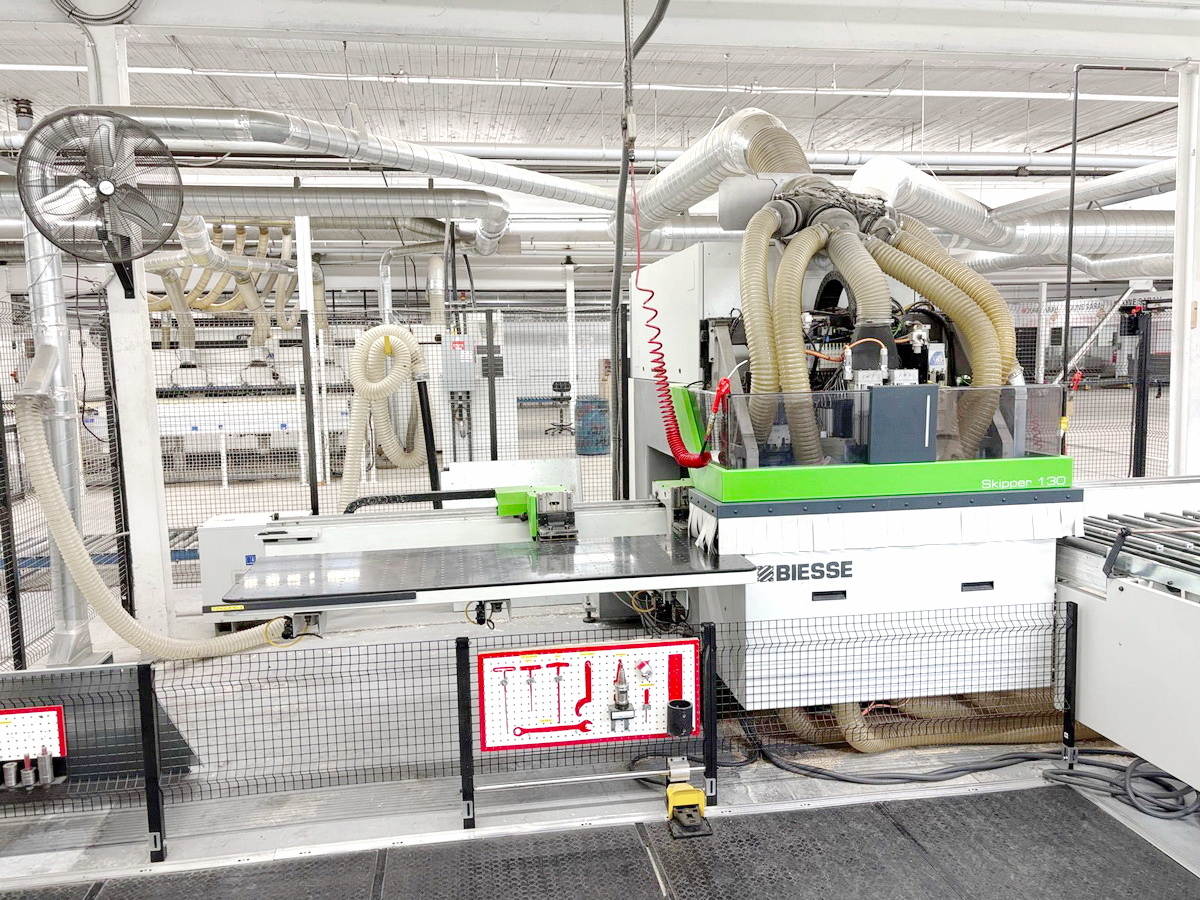
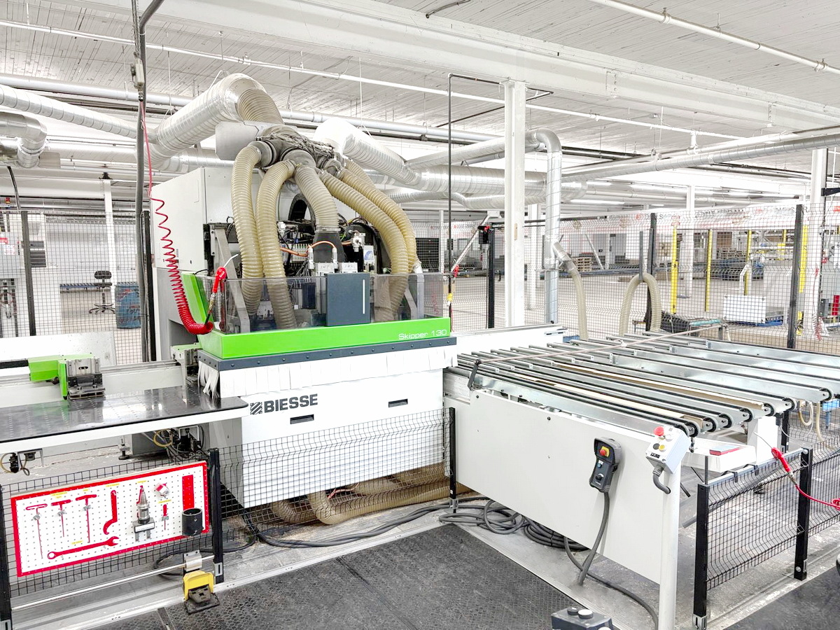
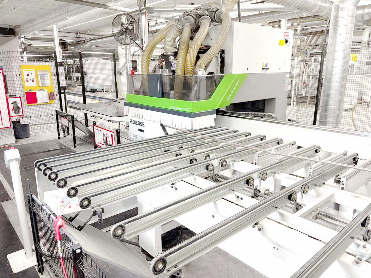
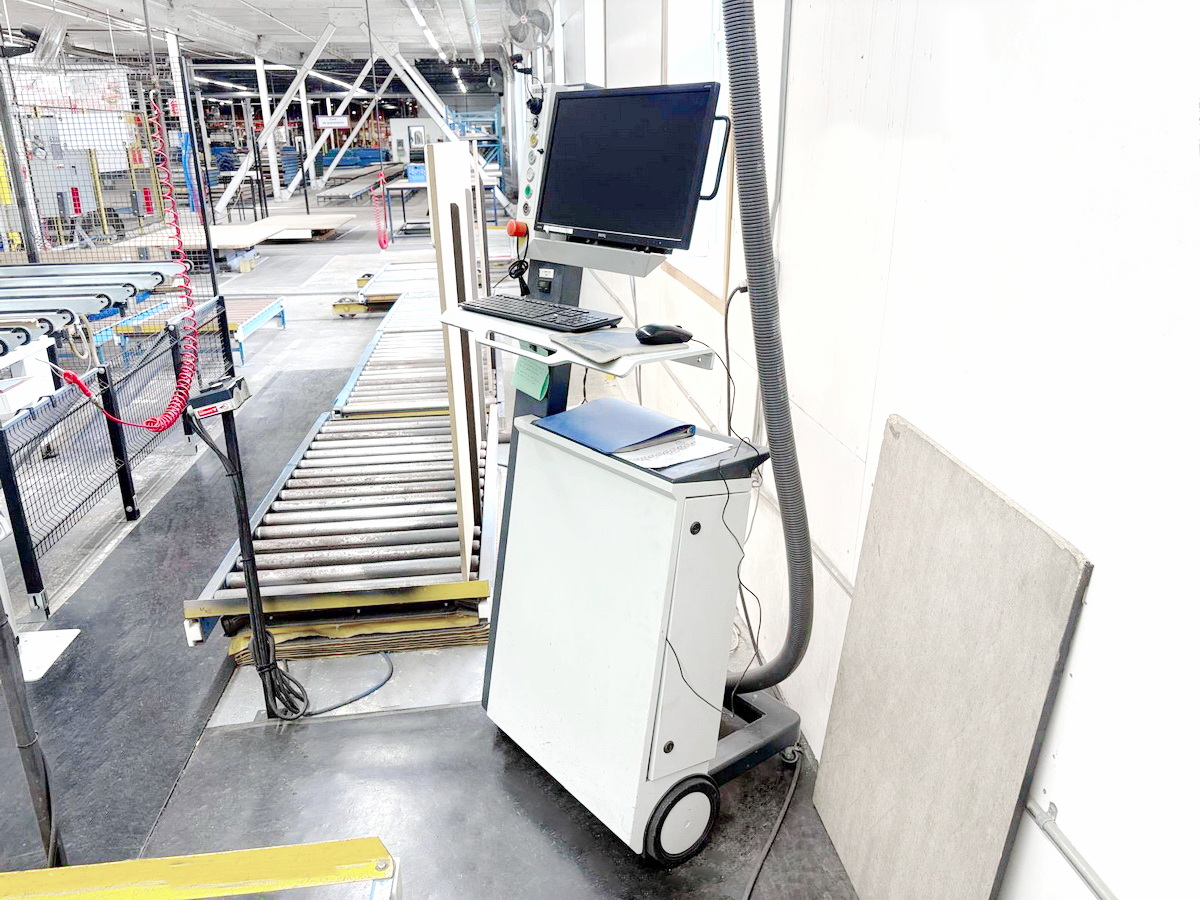
C.N.C. WORKING CENTER
BIESSE
Skipper 130
Technical details:
C.N.C. WORKING CENTER with 3 axes (X-Y-Z) - Goose-neck type
Movable panel (workpiece), static working head, Horizontal position of the panel (workpiece)
Numerical Control with Software BiesseWorks (Separate electric and command cabinet)
Safety cabin (enclosure) of the working head, Front emergency carpets
In-feeding working table (panel support)
No. 2 Workpieces fixing clamps (for the panels introduction in the working area)
Out-feeding table (with motorized belts)
Minimum workpieces dimensions (X - Y - Z) mm 90 x 70 x 8 (ca.)
Maximum workpieces dimensions (X - Y - Z) mm 3000 x 1300 x 60 (ca.)
Two panels that can be processed simultaneously (on the Z-axis)
Automatic panel dimension detection system (on the X and Y axes)
BOTTOM WORKING UNITS (BH41):
No. 31 Independent vertical boring spindles (No.) 31
No. 10 (8 X + 2 Y) Independent horizontal boring spindles
No. 1 Circular Grooving Saw (on X axis) dia. (mm) 160 (N° 1 x kw 5)
No. 1 Vertical electro-spindle ISO 30 (N° 1 x kw 6,5)
No. 1 Horizontal electro-spindle (N° 1) on the Y axis
TOP WORKING UNITS (BH41):
No. 31 Independent vertical boring spindles (No.) 31
No. 10 (8 X + 2 Y) Independent horizontal boring spindles
No. 1 Circular Grooving Saw (on X axis) dia. (mm) 160 (N° 1 x kw 5)
No. 1 Vertical electro-spindle ISO 30 (N° 1 x kw 6,5)
No. 1 Horizontal electro-spindle (N° 1) on the Y axis